Stationary Process Editor
Overview
The Stationary Process Editor (SPE) allows users to create and manage stationary processes, which model the onsite transformation of inputs into outputs within a specific production pathway. Each process is defined by its associated inputs, products, including both the main product and any co-products, and the specific conversion technologies employed during manufacturing. Along with transportation processes, stationary processes serve as the fundamental building blocks used to construct comprehensive pathways and pathway mixes.
Examples: Refining of a fuel precursor into usable product, production of a material, etc.
The SPE has two bottom tabs:
- General Information Tab
- Usage Tab
The functionality of the usage tab is explained within the relevant section within the Tab Navigation Section.
General Information Tab
The general information tab contains several subsections that define each part of a stationary process:
- General Information
- Main Output
- Inputs
- Input Groups
- Coproducts
- Non-Combustion Emissions & Wastes
- Carbon Relations
General Information
The general information setion consists of:
- Name
- Urban share
- Country
- 4-Digit NIACS Code
- Notes
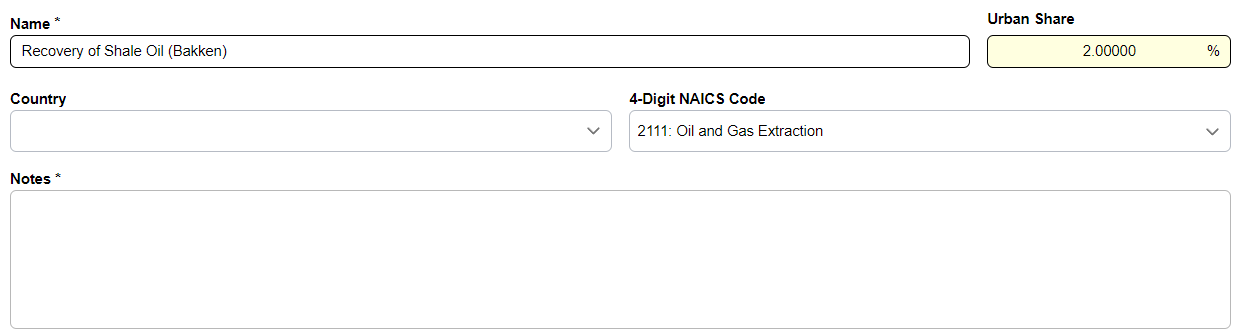
Urban Share
The Urban Share is a critical parameter used to determine the geographic distribution of emissions. It specifically represents the fraction of a stationary process's operation that occurs within a densely populated urban area.
Main Outputs
The main output section allows the user to define a given output for a process that represents the final desired product.
Required
A stationary process must have one, and only one main output.
Main Output Components
- Amount
- Losses: Can be expanded by clicking the carat on the left side
- Loss may be entered by amount or rate (%)
- When one is filled, the other will auto-populate with the calculated equivalent
- Amount produced after losses
- Emissions produced by evaporation
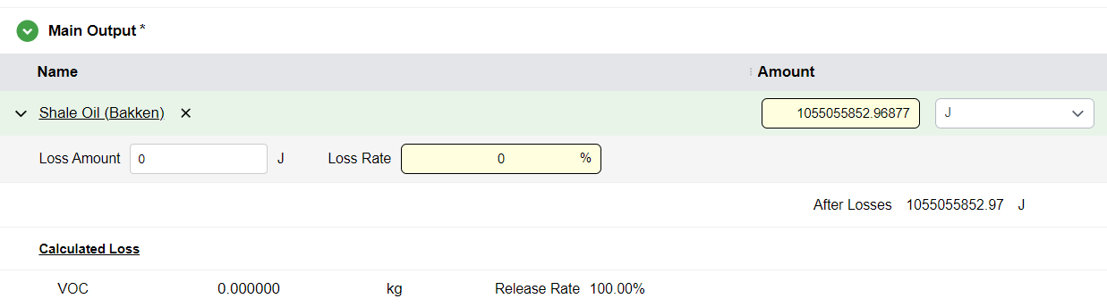
Emissions produced by evaporation
For the main output resource, any elements declared within the Releases Due to Loss section of the Flow Editor are explicitly accounted for in the model's mass balance. These values are displayed as calculated losses and are directly integrated into the overall pathway results.
Inputs
The inputs section of the SPE allows the user to designate one or more inputs to the stationary process. The inputs defined represent the necessary resources to produce the specified amount of main output and the co-products if a co-product exists.
Adding Inputs
- Hover over the Inputs subsection title
- Click the
+icon - Search for a given resource
- Click on it to add an input
Input Components
- Amount
- Source of the input
- Source pathway or pathway mix (if relevant)
- Conversions used by that input
- Emission ratios
Source
A Source represents the upstream supply chain required to produce the resource used as an input. By default, this value is set to Output of a Previous Process, meaning the upstream connection is defined at the pathway level rather than being a fixed attribute of the stationary process itself. This design provides significant modeling flexibility, as it allows a single process to be reused across multiple pathways while specifying unique sources for its inputs depending on the specific pathway context.
Single Pathway & Pathway Mix
The options for Single Pathway or Pathway Mix are only available when at least one corresponding entry has been defined. Beyond this requirement, the software provides the flexibility to reuse existing pathways for compatible resources as defined in the Flow Editor. For instance, pathways and mixes where the primary output is Conventional Diesel can be utilized for Diesel for Non-Road Applications. This functionality significantly minimizes the administrative burden of creating redundant pathways and manual connections for resources with similar profiles.
Internal Product
In the context of stationary processes and pathways, a resource is classified as an internal product when it is generated within the process boundary but is not the final output intended for the market. Instead, it serves as an intermediate flow that is consumed or used onsite.
Adding Conversions
- Click the carat next to the input name
- Click the
+icon next to the conversion label - Each conversion has:
- Share percentage of the input
- Checkbox for whether the conversion is accounted for in carbon balancing
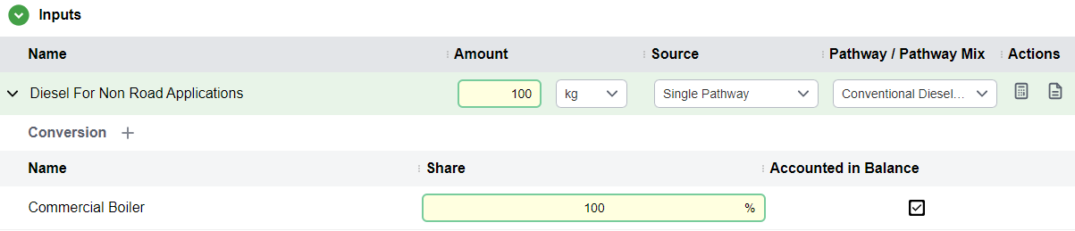
Accounted in Balance
If the Accounted in Balance item is checked, the emissions from this Conversion will be used in the emissions of the process. If not checked, the Technology is not used in the calculations.
Negative Share
If a negative share is assigned to a Conversion, the software automatically inverts the sign of the defined emission factors. For instance, if a Natural Gas boiler has a CO2 emission factor of 5.500e-8 kg/J, and the Conversion share is -100%, the calculation engine will process this value as -5.500e-8 kg/J.
Emission Ratios
This option allows you to specify emissions that are not conversion-related. For example, when nitrogen is used as a fertilizer, it vaporizes into some gases.
- Click the calculator icon in the actions column for an input
- A side panel opens
- Add one or more emissions produced by the input
- Specify the ratio of production
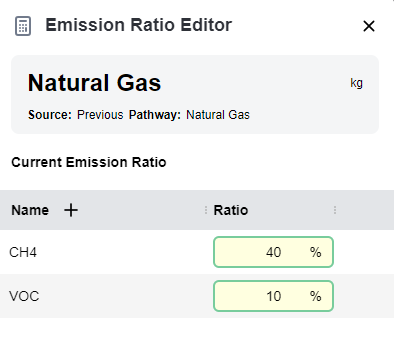
Warning
The percentages entered within the editor correspond to the mass-emission ratio. To ensure accurate calculations, the physical properties of the input resource must be fully defined so that the software can perform the necessary conversion to a mass basis. If the conversion cannot be done, the ratio emissions will be 0 for that input.
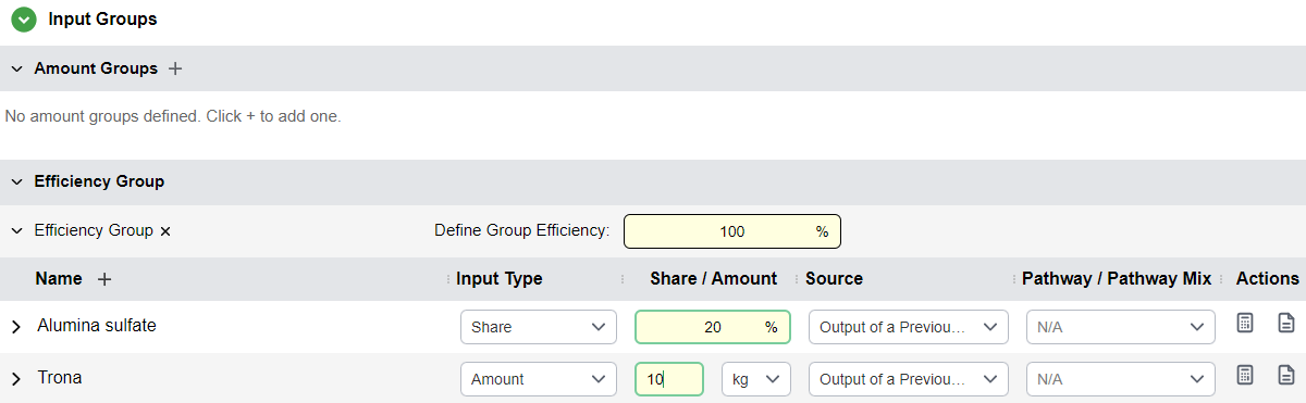
Input Groups
Input groups are like inputs but allow the user to group several inputs into a group. This can allow the user to specify inputs by an overall group amount or efficiency, for when multiple inputs together combine to one total (For example, Electricity coming from multiple sources being defined as percentage shared of one total energy amount).1
Types of Input Groups
- Efficiency Group: Overall group efficiency expressed as a percentage (only one or none per process)
- Amount Groups: Overall group amount as a numeric input with units (can have multiple)
Inputs Within Input Groups
Inputs within an input group may either be represented as:
- A share of the input group
- An amount
All other features of inputs within input groups are the same as regular inputs.
Required
Be sure that inputs within an input groups can be properly converted between dimensionality; otherwise, software will raise an error.
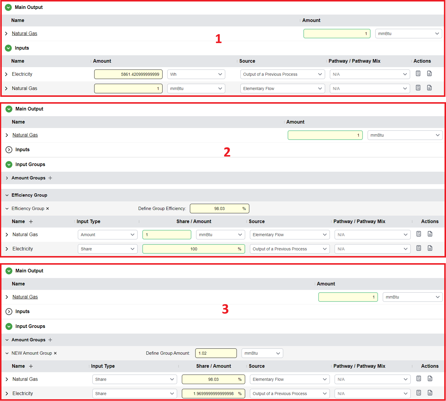
The SPE allows users to organize inputs into groups to achieve the same mass-balance results as standard declarations while gaining additional analytical insights. For example, using an Efficiency Group enables the expression of inputs relative to the specific amount required to produce a desired unit of primary output, providing critical data on the material use efficiency of the process. Alternatively, the Group Amount configuration allows a total supply to be defined and distributed among various materials; this is particularly effective when the total energy requirement is known but the specific "matrix of carriers", such as a flexible mix of different potential fuel sources, must be adjusted within the model.
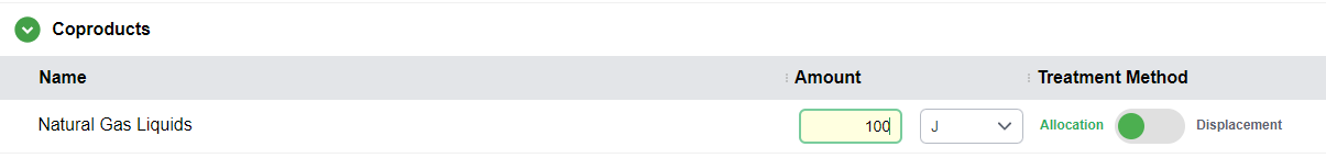
Coproducts
Coproducts represent additional outputs of a stationary process.
Adding Coproducts
- Click the
+icon next to the Coproducts subsection title - Search for a resource and hit enter to add it
- Coproducts have an amount and unit of output
Treatment Methods
The user may set the coproduct handling method by clicking on either the Allocation or Displacement label. Note that the text of the label must be clicked to open the displacement editor.
Displacement Method
Opens a side panel for the user to enter displaced products:
- Click the
+icon next to the Resources header in the table - Specify a source to displace from in the dropdown under the source column
- Add the displacement ratio in the ratio column
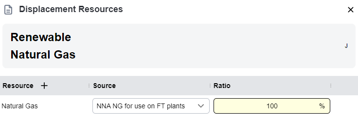
If the displacement method is selected, the displaced materials and upstreams need to be defined. In above fugure Renewable Natural Gas is displacing the pathway NNA NG for use on FT plants for Natural Gas.
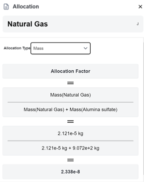
Allocation Method
A side panel opens where the user can select the allocation type:
- Mass
- Energy
- Market
- Casual
Mass, Energy, and Market Allocation
The allowed allocation method available will vary according to the physical properties available for all the output materials. Upon selecting a valid choice, the allocation will be calculated and displayed.
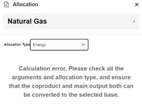
Calculation Error
If a given allocation method is invalid due to the main output and coproduct not sharing the required properties (e.g., trying to use energy allocation when either the main output or coproduct is expressed in mass-based units and does not have a heating value), a calculation error will occur and the user will be notified.
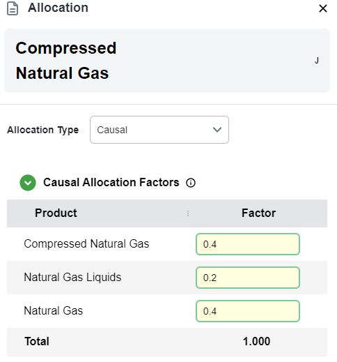
Casual Allocation
Causal Allocation requires the user to input the allocation factor per coproduct and main output. The allocation factors should add up to 1.000, as shown in the total column at the bottom of the table.
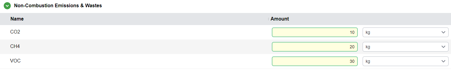
Non-Combustion Emissions & Wastes
The Non-Combustion Emissions and Wastes section allows users to represent the residual, fugitive, or secondary environmental outputs of a stationary process that are not captured within a primary Conversion (such as a combustion reaction or a specific chemical transformation). While Conversions model the intended stoichiometric or thermal processing of resources, this section accounts for the unintended or auxiliary releases that occur within the facility boundary.
Adding Emissions
- Click the
+icon that appears when hovering over the Non-Combustion Emissions subsection header - Emissions added to the table have an amount specified for the overall process
Carbon Relations
This feature allows users to define specific relationships between inputs and outputs, expressed as mass-based weights. These weights specify the "chemical" contribution of an input to the primary output. For example, while an ethanol plant consumes various resources, ethanol is physically derived from corn fermentation; other inputs, such as natural gas or electricity, provide process heat and power. In this case, a 1:1 ratio is defined between the ethanol output and the corn feedstock. This parameter is critical for calculating Biogenic Credits. When ethanol is eventually combusted, the model traces the carbon back to the original biomass feedstock. Consequently, the CO2 emitted during combustion is classified as biogenic, resulting in a negative value or "credit" within the process results.
A table is shown, with every output being a row, and every input being a column.
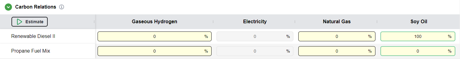
When Cells are Editable
Cells are editable if one of the following conditions are met:
- If the input is a primary resource and has a biogenic carbon content, OR
- If the Input comes from previous output, a source pathway or mix, and is not an energy input
Additionally:
- The output flow must not be energy flow
- There is an Estimate button to allow PyGREET to calculate the carbon relations table bassed on carbon content and mass of inputs and outputs