Vehicles Editor
Overview
The Vehicle Editor in PyGREET is a LCA tool for defining, customizing, and analyzing vehicle-specific data. It supports the modeling of energy use and emissions over a vehicle's full lifecycle—from manufacturing to operation and end-of-life. Vehicles can either be standard, or non-standard vehicles. Non-standard vehicles contain one or more materials or fuels that have a source type of "Output of a Previous Process." These vehicles cannot have results generated within the vehicle editor, and instead must be added as blocks to a pathway in the Pathway Editor
The vehicle editor consists of three bottom tabs:
- General Information
- Results
- Usage Tab
The functionality of the usage tab is explained within the relevant section within the Tab Navigation Section.
Info
Usage tab are only important for those vehicles used as part of pathways.
General Information
The general information section consists of four sections, along with the name, notes, and vehicle type.
Vehicle Type
The vehicle type is chosen as a dropdown.
Vehicle Details Section
Several parameters to describe the vehicle:
- Lifetime VMT
- Payload and passengers
- Electric range
- Urban share
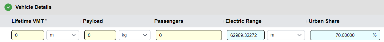
Lifetime VMT
The Lifetime VMT (vehicle miles traveled) is specific to the use of vehicle construction components. If we account for components, we must then know how many times they are going to be used or replaced over the lifetime of the vehicle in order to account for upstream energy and emissions associated with them.
Payload
The Payload is optional, if a payload is defined, then the results can be normalized using that payload and displayed in X/(ton mi) where X represents either an energy or a mass.
Passengers
The number of passenger is also used in the same manner, if passengers are defined then results can be expressed per passenger mile.
Electric Range
It is the total distance a vehicle can travel using only the energy stored in its onboard battery pack, without the assistance of an internal combustion engine. This parameter is used to automatically calculate VMT Share
Urban Share
The Urban Share for a vehicle defines the percentage of total VMT that occurs within densely populated urban areas. This parameter is used to geographically allocate tailpipe and non-exhaust emissions, which is essential for assessing the local impacts of criteria air pollutants.
Vehicle Cycle Modeling Section
This section allows users to add various materials related to the construction of the vehicle.
Major Groups
Materials are broken down into five groups:
- ADR (Assembly, Disassembly, and Recycling)
- Battery
- Components
- Fluids
- Others
Each section can be expanded or hidden by clicking on the carat on the major group row.
Adding Materials
- Click the
+icon next to the group title - Search for and click on the desired resource flow
- For each material declare unitary quantity, number of units, replacement, source specification
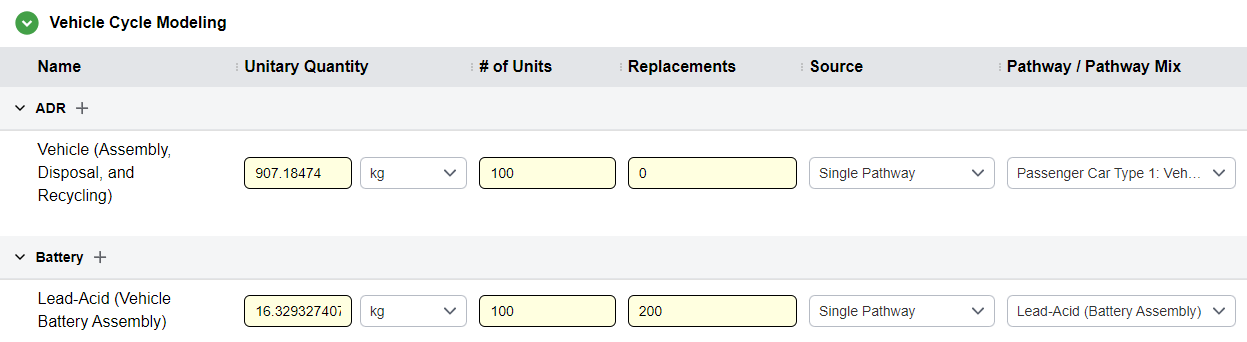
Unitary Quantity
The mass of a single item of this component.
# of Units
The number of units or number of unitary quantities on this vehicle.
Replacements
The number of replacement for the all units on this vehicle over it’s lifetime.
Source
For each of these vehicle construction items, a pathways is associated so that the algorithms can use the upstream for the production of these components in the WTW results.
Warning
The Lifetime VMT of the vehicle must be defined if any materials are added to the vehicle.
"Output of a Previous Process
If a material source has a source type of "Output of a previous process," the vehicle is considered non-standard. The vehicle using this material must be modeled in the Pathway Editor to connect upstream pathways and generate results.
Non-Combustion Emissions Table
The non-combustion emissions (or non-exhaust emissions) are not related to the internal combustion engine operation, but to external factors, such as tire and brake use or gasoline evaporation.
This table functions similarly to the table located in a stationary process. Serves to represent all emissions produced during the operation of a vehicle. For more information, see the Non-Combustion Emissions table located in the Stationary Process Editor
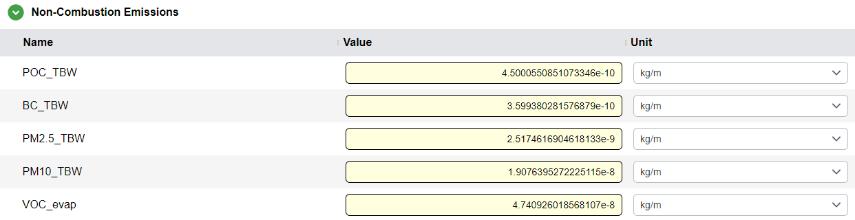
Note
Emissions are expressed per unit of distance traveled.
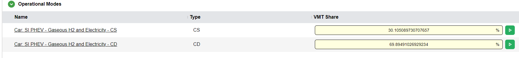
Operational Modes Table
The Operational Modes Table allows users to add one or more operational modes to a vehicle. Operational modes represent the fuel used and emissions generated by vehicle operation, and can be created or edited in The Operational Mode Editor. The Operational Modes table consists of three columns: The name of the Operational Mode, the type of the Mode, and the VMT Share. Operational Modes can be added by clicking the + icon that appears when hovering over the Operational Modes section header.
The name of a operational mode may be clicked on to open The Operational Mode Editor to edit the respective mode.
Warning
The VMT Share of all operational modes must total to 100%.
Automatic VMT Share Calculation
For vehicles that contain one or more operational modes that use electricity, the user may click the green > icon to calculate the VMT share automatically.
Results
Important
Results can only be generated in the Vehicle Editor for standard vehicles (i.e vehicles with no material or fuel that have a source type of "Output of Previous Process.") Non-standard vehicles must instead be modeled in the Pathway Editor. However, results for non-standard vehicles within the Pathway Editor have the same format as results for standard vehicles, described below.
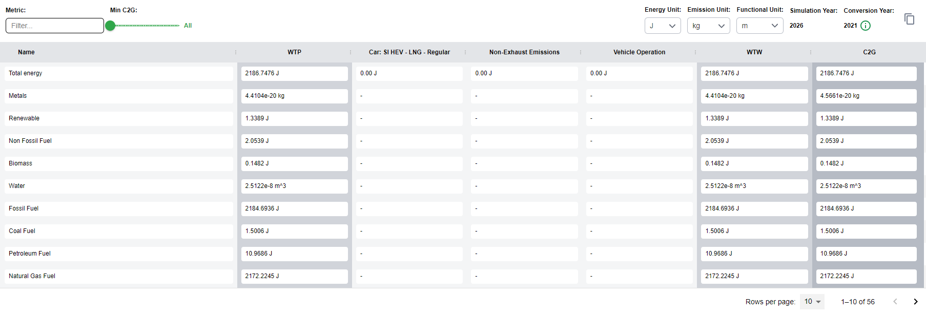
Vehicle results are calculated and then broken down into individual sections in a large table.
Each row in the table represents one type of emission. The Vehicle Results table splits rows across multiple pages to improve performance. The amount of rows per page, and what page is visible, can be controlled in the bottom right of the editor.
Results View Controls

- Metric: The rows of the results table can be filtered to a desired metric / resource.
- Metric value slider: Filter the table based on a minimum value for C2G metrics, e.g., showing metrics >= 1e-5
- Energy Unit, Emission Unit, and Functional unit: Can be set at the top of the results view
- Simulation year: Displayed
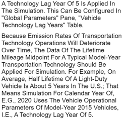
- Technology year: Displayed with an information circle explaining the technology lag year
- Copy Table: Copies the table to the clipboard for pasting into Microsoft Excel or similar programs
Results Columns
Results are broken down into the following columns:
- WTP (Well-to-Pump) - highlighted
- Columns for each energy source in each operational mode
- Non-Exhaust Emissions
- Total Vehicle Operation
- WTW (Well-to-Wheel) - highlighted
- One column for each material group:
- Components
- ADR
- Fluids
- Battery
- Others
- C2G (Cradle-to-Grave) - highlighted
Info
The results for WTP, WTW, and C2G are highlighted to stand out as the total results per system boundary.